Hypersonic Space-Shot
Liquid Bipropellant Sounding Rocket “Eureka”
The Base11 Space Challenge has inspired students to reach for the edge of space with liquid propulsion for the first time in history. Specifically, to design, build, and fly a liquid bipropellant rocket to an altitude of 100km above sea level.
In my role as Chief Engineer for Space Enterprise at Berkeley, I personally developed dozens of components and integrated systems for the Eureka-1 rocket, including primary design of the combustion chamber, nozzle, pressurization system, aerodynamic surfaces, nose cone thermal protection, and radio communications system, as well as primary flight simulation including Monte-Carlo landing site prediction.
In addition to the components I designed, I led and oversaw the PDR and CDR process for all rocket components and integrated systems, gaining familiarity with sensors and data acquisition, composite structure design and fabrication, liquid bipropellant injectors, loading & handling procedures for LOX and LPG, additive manufacturing processes including DMLS and SLA, and CNC machining.

Eureka-1 BURNS FOR SPACE
Before I gained funding for the project or additional collaborators, I published and presented the results of my feasibility design study in the 2018 IEEE Aerospace Conference. The link to that design study including the full text of my paper is available here.

Multi-Composite carbon nozzle
Building on the legacy of “Sparky”, Eureka will utilize a carbon-fiber overwrapped composite nozzle that uses CFoam-30 as a refractory non-ablative thermal barrier and chamber liner.

MOnte-CArlo Flight Dynamics & simulation
Utilizing a combination of custom-written simulators and industry-standard tools such as STK and Rocksim Pro, I have simulated and planned Eureka’s flight in anticipation of the FAA flight waiver process.
Pictured: Nominal Flight Trajectory using historical windage data from CUSF 2.5

Systems fabrication
In preparation for static testing, one of two main propellant tanks for the Eureka is inspected and cleaned. These tanks were donated by Samtech International, a title sponsor of Space Enterprise at Berkeley and a major contractor for companies like ULA and SpaceX.
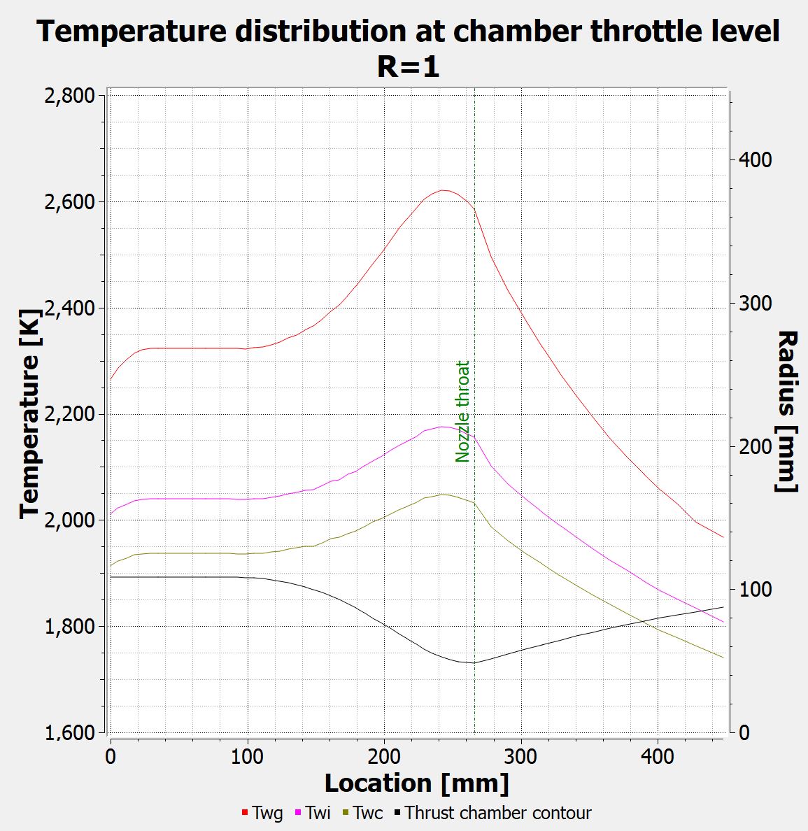
NOZZLE TEMPERATURE SIMULATION
I have conducted detailed analysis of the thermal and mechanical loads on the interior of the rocket nozzle utilizing both vendor-provided product specs and results from empirical testing of sample materials.

Engine transient state modeling
By computing propellant flow rates and gas dynamics over short intervals, I developed a reasonable approximation of the startup behavior of Eureka’s engine system.
Future improvements will consider residence times of propellants in the chamber (current models assume that after combustion, propellants instantly leave the nozzle) and an improved stochastic module incorporating regulator output variability and manufacturing tolerances.

Design reviews
As SEB Chief Engineer, I am responsible for the conceptualization, PDR, and CDR process for all vehicle components, test articles, and ground support equipment.
In this image, I am presenting the PDR for the Eureka-1 propulsion system, a liquid bipropellant utilizing liquid oxygen and sub cooled HD-5 (90% Propane, 5% Butane, 5% Propylene).

Engine Internal stress analysis
Using Classical Lamination Theory and assuming an elastic inner liner (a valid assumption for high-temperature carbon foam), the stress in the exterior Carbon Fiber shell can be computed and solved.

Carbon foam test articles
To verify composite material performance, test samples of the CFoam material, some with additional ablative coatings, thermal insulation barriers, and other similar devices.
This particular sample shows a CFoam disc coated in an ablative furnace cement manufactured by SGL. The cement failed testing because it was discovered that the cement contains binders which outgas during full cure. The outgassing introduces large, unavoidable voids in the final rigidly cured cement.

STAYING COOL AT 2000 DEGREES
The above video shows FLIR footage of one of the heat and chemical resistance tests conducted on the CFoam test articles prepared earlier.
By calibrating the output intensity and chemical composition of an oxy-acetylene torch, we were able to match the thermal and chemical environment found at the throat of Eureka’s liquid engine and determine the amount of insulation required to maintain integrity of the carbon fiber structural shell of the engine.